- Best quality
- Quick assembly
- Longevity
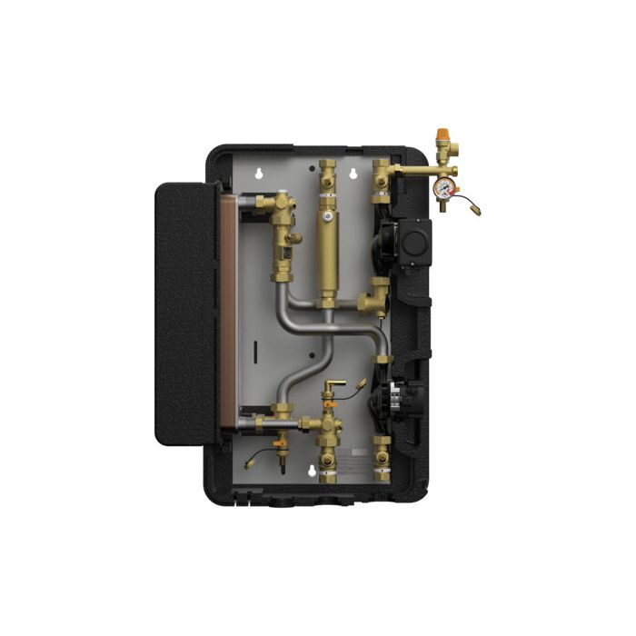
Solex|SolarBloC®
Solar
thermal
systems
SolexMaxi HZ up to 100 m²
Application range: up to 100 m² collector surface
with heat quantity measurement according to the BAFA promotion directive for solar thermal systems
The CE-conformity of the installation has been certified according to DIN EN 60335.
All connections 1" internal thread
Premounted on steel wall bracket
can be easily mounted to the wall
All fluid-carrying parts made of brass or stainless steel, fully assembled - self-sealing or flat gaskets
Full port ball valves
Check valve in the solar and secondary circuit, can be opened, 200 mm wc, especially for solar systems, prevent unwanted circulation
Airstop in the flow line
for permanent deaeration of the solar fluid
With high-efficiency pumps by Grundfos, premounted and prewired, adapted to the performance of the transfer station, pumps can be isolated completely, no draining during servicing
Flush and fill unit integrated
two fill and drain valves permit filling and flushing the primary circuit, secondary circuit with pressure relief valve at the highest point of the heat exchanger
FlowRotor, flow meter for speed control of the secondary pump, depending on the performance and heat quantity balancing (secondary)
Solar safety group
Solar pressure relief valve 6 bars, pressure gauge resistant to high temperatures 0-6 bar with valve, flat sealing connection for a diaphragm expansion tank, secondary side with pressure relief valve, 6 bar
Compact design insulation with optimised function
made of durable elastic EPP, 100 % insulated valves and fittings - excellent ventilation and cooling of the pumps, minimal heat losses
High-efficiency plate heat exchanger
generously dimensioned, for transmitting high performances with low temperature differences, completely integrated into the insulation
Safety instructions The installation and commissioning as well as the connection of electrical components require technical knowledge commensurate with a recognised vocational qualification as a fitter for plumbing, heating and air conditioning technology, or a profession requiring a comparable level of knowledge [specialist]. The following must be observed during installation and commissioning: - relevant local and national regulations - accident prevention regulations of the professional association - instructions and safety instructions mentioned in these instructions.
WARNING Danger of scalding due to the escape of hot fluids! With pressure relief valves, there is a risk of scalding due to the escape of vapour or hot fluid. Please ensure for each pressure relief valve that no personal injury or material damage may occur due to possibly escaping medium. - Install a discharge line. - Observe the instructions regarding the pressure relief valve. - The pressures for the expansion tank calculated by the plant designer and the operating pressure of the installation must be set.
CAUTION Personal injury and material damage due to overpressure! Closing both ball valves in the primary circuit will separate the safety group from the heat exchanger. A rise in temperature in the storage tank may result in high pressures, which may lead to personal injury and material damage! - Only close the ball valves for service and maintenance. - When closing the ball valves in case of servicing, also put the pumps out of operation and close the ball valves / piston valves of the secondary circuit. CAUTION Risk of burns! Valves, fittings and pump may heat up to more than 100 °C during operation. The insulating shell must remain closed during operation.
NOTICE Material damage due to mineral oils! Mineral oil products cause lasting damage to seals made of EPDM, whereby the sealant properties get lost. We do not assume liability nor provide warranty for damage to property resulting from sealants damaged in this way. - It is imperative to avoid that the EPDM sealing elements of the unit get in contact with substances containing mineral oils. - Use a lubricant based on silicone or polyalkylene and free from mineral oils, such as Unisilikon L250L and Syntheso Glep 1 of the Klüber company or a silicone spray.

